User Guide
Introduction
Welcome to the CNF Reference Architecture user guide. This guide provides instructions on how to run a sample containerized networking application in a multi-node Kubernetes cluster comprised of AArch64 machines.
This reference solution is targeted for a networking software developer or performance analysis engineer who has in-depth networking knowledge, but does not know AArch64 architecture necessarily.
Mastering knowledge on certain open source projects, e.g., Ansible, Kubernetes, DPDK, will help gain deeper understanding of this guide and reference solution more easily.
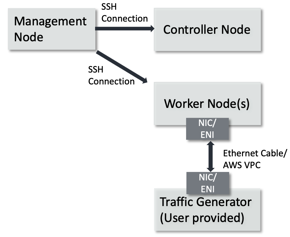
This guide is intended to describe complex and practical uses cases requiring complex test setup. By following the steps of this guide to the end, you will setup a multi-node Kubernetes cluster. One machine will serve as the Kubernetes controller and host a private Docker registry to hold custom container images. The worker nodes will run Application Pods, like DPDK Testpmd. The multi-node Kubernetes cluster topology is shown below.
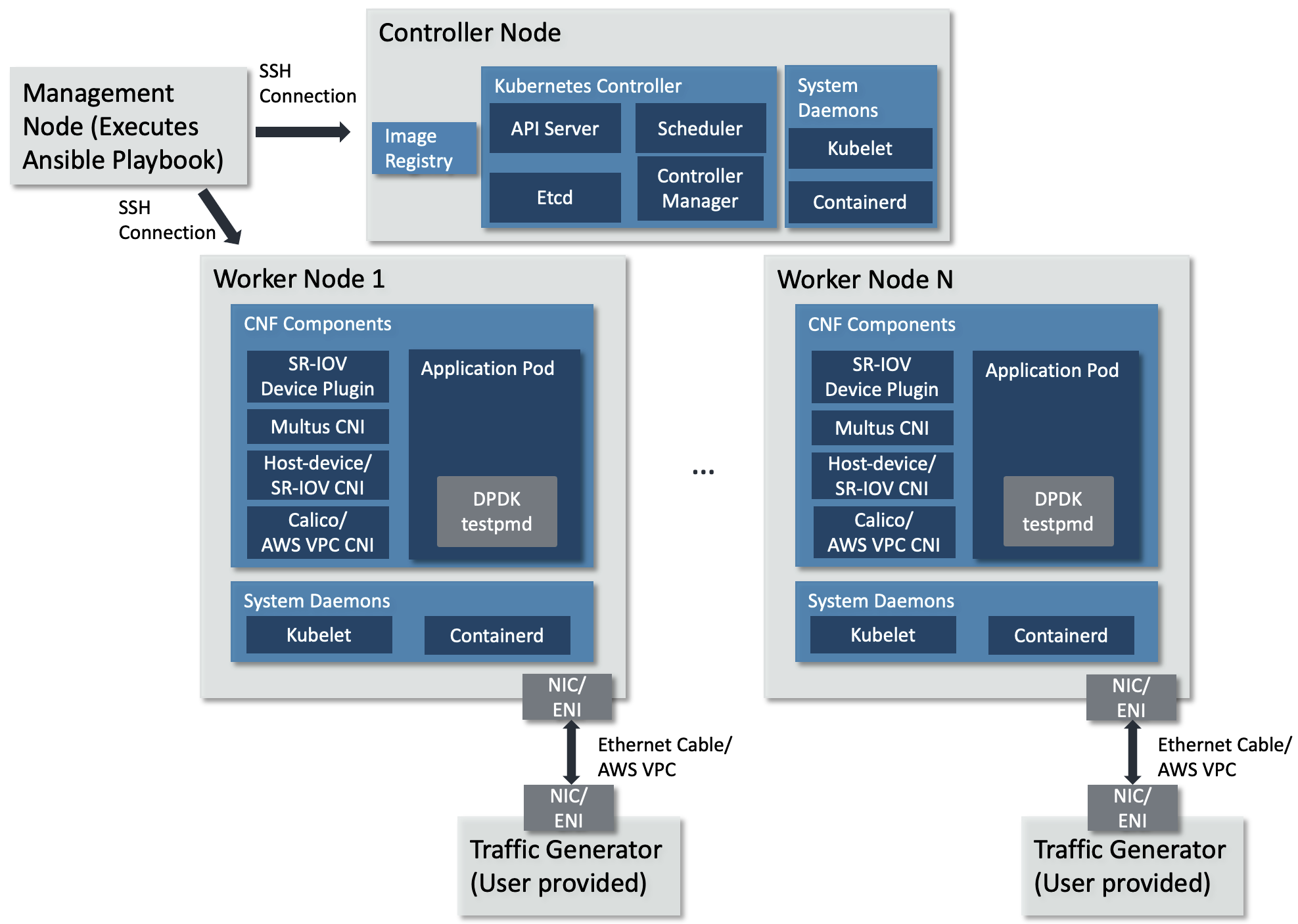
Multi-node Kubernetes cluster topology
The topology diagram above illustrates the major components of the deployment and their relationship.
DPDK testpmd application, implements 5-tuple swap networking function in software and forwards packets out the same port which receives them.
TG (Traffic Generator), generates and sends packets to the worker node’s NIC card via the Ethernet cable. It can be hardware TG, e.g., IXIA chassis, or software TG running on regular server, e.g., TRex, DPDK Pktgen, Scapy.
Management Node, can be any bare-metal machine, VM, or container. It is used to download the project source code, login to the controller and worker nodes to create the Kubernetes cluster and deploy the application.
Infrastructure Setup
This guide can be run on physical hardware or on AWS EC2 cloud instances.
This guide requires the following setup:
Physical Hardware Setup
Controller Node can be any machine that has a network connection to the other machines in the Kubernetes cluster. The solution is tested against an AArch64 machine as the controller node.
Hardware Minimum Requirements
The Controller Node has the following hardware requirements:
Minimum 1GHz and 2 CPU cores
Minimum 8GB RAM
Connection to the internet to download and install packages
Connection to the worker nodes
Software Minimum Requirements
The following items are expected of the Controller Node’s software environment:
Controller Node is running Ubuntu 20.04 (Focal)
Admin (root) privileges are required
The Fully Qualified Domain Name (FQDN) of the Controller Node can be checked with
python3 -c 'import socket; print(socket.getfqdn())'command. See Troubleshooting if the proper FQDN is not shown.
Worker Nodes are any number of AArch64 architecture machines. NIC card is plugged into a PCIe slot and is connected to a traffic generator with an Ethernet cable.
Hardware Minimum Requirements
The Worker Nodes have the following hardware requirements:
AArch64 v8 CPU
Minimum 1GHz and 4 CPU cores
DPDK compatible NIC
Connection to the internet to download and install packages
Minimum 8G of RAM
Support 1G Hugepages
Software Minimum Requirements
Worker node is running Ubuntu 20.04 (Focal)
Admin (root) privileges are required
PCIe address of the NIC port(s) attached to the traffic generator is confirmed with
sudo lshw -C network -businfoCPU cores are isolated and 1GB hugepages reserved via required Linux command line parameters. See FAQ for more details.
There can be any number of worker nodes. To use a single-node cluster, refer to the Quickstart Guide.
Management node can be any bare-metal, VM, or container. The management node is used to download the repository, access the cluster nodes via
sshand configure the Kubernetes cluster by executing an Ansible playbook. The Ansible playbook is executed locally on management node and it configures the cluster nodes viassh.
Software Minimum Requirements
Can execute Ansible
Can
sshinto each cluster node using SSH keys. See FAQ for more details.Admin (root) or
sudoprivileges are required
TG can be any traffic generator capable of generating IP packets.
AWS EC2 Setup
Controller Node can be any EC2 AArch64 machine that has a network connection to the other machines in the Kubernetes cluster.
EC2 Requirements
The Controller Node has the following hardware requirements:
c6gn.xlarge or c7gn.xlarge (or larger) instance
Connection to the internet to download and install packages
Connection to the worker nodes
EC2 instance is associated with the required AWS VPC CNI IAM policies, in addition to the AmazonEC2ContainerRegistryReadOnly policy.
Software Minimum Requirements
The following items are expected of the Controller Node’s software environment:
Controller Node is running Amazon Linux 2
Admin (root) privileges are required
Worker Nodes are any number of AArch64 EC2 instances meeting the following requirements:
EC2 Requirements
c6gn.xlarge or c7gn.xlarge (or larger) instance type
Secondary ENI attached, with the
node.k8s.amazonaws.com/no_manage: truetag applied. The ENI’s PCIe address is known
It should be
0000:00:06.0Connection to the internet to download and install packages
Software Requirements
Amazon Linux 2 AMI
awsCLI installed, with permission to describe-instance-typesCPU cores are isolated via the
isolcpusin the Linux command line parameters. See FAQ for more detailsAt least one 1G hugepage is available. To easily allocate one, add the relevant Linux command line parameters as describe in the FAQ
SSH access enabled via SSH keypair
Admin (root) or
sudoprivilegesEC2 instance is associated with the required AWS VPC CNI IAM policies, in addition to the AmazonEC2ContainerRegistryReadOnly policy.
Management node can be any bare-metal, VM, or container. The management node is used to download the repository, access the DUT via
sshand configure Kubernetes cluster by executing an Ansible playbook. The Ansible playbook is executed locally on management node and it configures the DUT viassh.
Software Minimum Requirements
Can execute Ansible
Can
sshinto the DUT using SSH keys. See FAQ for more details.Admin (root) or
sudoprivileges are required
TG can be any traffic generator capable of generating IP packets. For EC2 deployment, this is typically another EC2 instance in the same VPC running a software based traffic generator, such as Pktgen DPDK.
Tested Platforms
This solution is tested on the following platforms.
Physical Hardware
Cluster Nodes
Ampere Altra (Neoverse-N1)
Ubuntu 20.04.3 LTS (Focal Fossa)
NIC
-
OFED driver: MLNX_OFED_LINUX-5.4-3.1.0.0
Firmware version: 16.30.1004 (MT_0000000013).
Intel X710
Firmware version: 6.01
Note
To use Mellanox NIC, install OFED driver, update and configure NIC firmware by following the guidance in FAQ.
Management Node
Ubuntu 20.04 system
Python 3.8
Ansible 6.5.0
AWS EC2 Instances
Cluster Nodes
c6gn.xlarge instance and c6gn.2xlarge instance
Amazon Linux 2
Kernel
5.10.184-175.731.amzn2.aarch64Security group settings
Security group settings added same as this Kubernetes Ports and Protocols guidelines
Additionally for allowing traffic between x86 and arm EC2 give permissions to all ports and protocol in inbound rules.
Secondary ENI attached at device index 1, with
node.k8s.amazonaws.com/no_manageset totrue
Management Node
Ubuntu 20.04 system
Python 3.8
Ansible 6.5.0
Prerequisite
Management Node
Management node needs to install dependencies, e.g., git, curl, python3.8, pip, Ansible, repo. Follow below guidelines on Ubuntu 20.04.
Make sure
sudois available and installgit, curl, python3.8, python3-pip, python-is-python3by executing$ sudo apt-get update $ sudo apt-get install git curl python3.8 -y $ sudo apt-get install python3-pip python-is-python3 -y
Install
ansibleandnetaddrby executing$ sudo python3 -m pip install ansible==6.5.0 netaddr
Note
Install the
ansibleand not theansible-corepackage, as this solution makes use of community packages not included in theansible-corepython package.
DUT
Complete below steps by following the suggestions provided.
Download Source Code
Unless mentioned specifically, all operations in this section are executed on management node.
Create a new folder that will be the workspace, henceforth referred to as
<nw_cra_workspace> in these instructions:
mkdir <nw_cra_workspace>
cd <nw_cra_workspace>
export NW_CRA_RELEASE=refs/tags/NW-CRA-2024.03.29
Note
Sometimes new features and additional bug fixes are made available in
the git repositories, but are not tagged yet as part of a release.
To pick up these latest changes, remove the
-b <release tag> option from the repo init command below.
However, please be aware that such untagged changes may not be formally
verified and should be considered unstable until they are tagged in an
official release.
To clone the repository, run the following commands:
repo init \
    -u https://git.gitlab.arm.com/arm-reference-solutions/arm-reference-solutions-manifest.git \
    -b ${NW_CRA_RELEASE} \
    -m cnf-reference-arch.xml
repo sync
Create Kubernetes Cluster
Unless mentioned specifically, all operations henceforth are executed on management node.
Create Ansible Inventory File
The Ansible playbooks in this repository are easiest to use with inventory files to keep track of the cluster nodes. For this solution we need one inventory file.
A template inventory.ini is provided at <nw_cra_workspace>/cnf-reference-arch/inventory.ini with the following contents:
[controller]
<fqdn_or_ec2_ip> ansible_user=<remote_user> ansible_private_key_file=<key_location>
; replace above line with DUT FQDN & optionally ansible_user and ansible_private_key_file.
; If an optional variable is not used, delete the entire key=<placeholder>.

[worker]
<fqdn_or_ec2_ip> ansible_user=<remote_user> pcie_addr=<pcie_addr_from_lshw> dpdk_driver=<driver_name> ansible_private_key_file=<key_location>
; replace above line with DUT FQDN, PCIe address, DPDK linux driver & optionally ansible_user and ansible_private_key_file.
; If an optional variable is not used, delete the entire key=<placeholder>.
Filling in of the inventory file differs between a physical hardware setup and an AWS EC2 setup.
Physical Hardware Inventory File
Under the [controller] heading, replace <fqdn_or_ec2_ip> with the FQDN of the Controller Node. Under the [worker] heading, replace <fqdn_or_ec2_ip> with the FQDN of a worker node, or an SSH alias for a worker node.
If the controller node is also a worker node, the FQDN should be the exact same under both the [controller] and [worker] headings.
<remote_user> specifies the user name to use to login to that node.
Replace <pcie_addr_from_lshw> with the PCIe address of the port on the worker node connected to the traffic generator.
If the worker node uses Mellanox ConnectX-5 NIC to connect the traffic generator, replace <driver_name> with mlx5_core. Otherwise, replace it with vfio-pci.
ansible_private_key_file should be set to the identity file used to connect to each instance if other than the default key used by ssh.
If multiple worker nodes are to be used, each one should be a separate line under the worker tag, with ansible_user, pcie_addr, dpdk_driver and ansible_private_key_file filled in per worker node.
As an example, if the user name used to access the cluster nodes is user1, the controller’s FQDN is dut.arm.com, the sole worker is reachable at worker-1 and is connected to the traffic generator on PCIe address 0000:06:00.1 with a NIC compatible with the vfio-pci driver, then inventory.ini would contain:
[controller]
dut.arm.com ansible_user=user1

[worker]
worker-1 ansible_user=user1 pcie_addr=0000:06:00.1 dpdk_driver=vfio-pci
Note
All PCIe addresses for a single node must work with the same DPDK driver. This solution does not support per-address DPDK drivers without modification.
If worker-1 also had PCIe address 0000:06:00.0 connected to a traffic generator, then inventory.ini would contain:
[controller]
dut.arm.com ansible_user=user1

[worker]
worker-1 ansible_user=user1 pcie_addr="['0000:06:00.1', '0000:06:00.0']" dpdk_driver=vfio-pci
If the same setup also included a worker-2 which is connected to a traffic generator on PCIe address 0000:09:00.0 with a Mellanox NIC, and used different-key.pem as the private key, then inventory.ini would contain:
[controller]
dut.arm.com ansible_user=user1

[worker]
worker-1 ansible_user=user1 pcie_addr="['0000:06:00.1', '0000:06:00.0']" dpdk_driver=vfio-pci
worker-2 ansible_user=user1 pcie_addr=0000:09:00.0 dpdk_driver=mlx5_core ansible_private_key_file=different-key.pem
AWS EC2 Inventory File
Under the [controller] heading, replace <fqdn_or_ec2_ip> with the primary IP address of the Controller Node. Under the [worker] heading, replace <fqdn_or_ec2_ip> with the primary IP address of a worker node.
<remote_user> specifies the user name to use to login to that node.
Replace <pcie_addr_from_lshw> with the PCIe address of the secondary ENI with tag node.k8s.amazonaws.com/no_manage: true. This is typically 0000:00:06.0.
Replace <driver_name> with igb_uio.
ansible_private_key_file should be set to the SSH key pair generated at instance creation.
As an example, if the user name to access the cluster nodes is ec2-user, the controller’s IP is 10.100.100.100, the sole worker’s IP is 10.100.200.200 the private key file is ssh-key-pair.pem, and the secondary ENI PCIe address is 0000:00:06.0, then inventory.ini would contain:
[controller]
10.100.100.100 ansible_user=ec2-user ansible_private_key_file=ssh-key-pair.pem

[worker]
10.100.200.200 ansible_user=ec2-user pcie_addr=0000:00:06.0 dpdk_driver=igb_uio ansible_private_key_file=ssh-key-pair.pem
If the same setup also included another worker node with primary IP 10.100.200.210 with a secondary ENI PCIe address of 0000:00:06.0 and used the same ec2-user and ssh-key-pair.pem, then inventory.ini would contain:
[controller]
10.100.100.100 ansible_user=ec2-user ansible_private_key_file=ssh-key-pair.pem

[worker]
10.100.200.200 ansible_user=ec2-user pcie_addr=0000:00:06.0 dpdk_driver=igb_uio ansible_private_key_file=ssh-key-pair.pem
10.100.200.210 ansible_user=ec2-user pcie_addr=0000:00:06.0 dpdk_driver=igb_uio ansible_private_key_file=ssh-key-pair.pem
If the worker with IP address 10.100.200.200 had another secondary ENI with the tag node.k8s.amazonaws.com/no_manage: true at PCIe address 0000:00:07.0, then inventory.ini would contain:
[controller]
10.100.100.100 ansible_user=ec2-user ansible_private_key_file=ssh-key-pair.pem

[worker]
10.100.200.200 ansible_user=ec2-user pcie_addr="['0000:00:06.0', '0000:00:07.0']" dpdk_driver=igb_uio ansible_private_key_file=ssh-key-pair.pem
10.100.200.210 ansible_user=ec2-user pcie_addr=0000:00:06.0 dpdk_driver=igb_uio ansible_private_key_file=ssh-key-pair.pem
Setup Kubernetes Cluster
Next, setup the Kubernetes cluster by executing the create-cluster.yaml playbook.
The playbook takes multiple override parameters that slightly modify its behavior.
Physical Hardware
To execute the playbook without any override parameters, run ansible-playbook -i inventory.ini -K create-cluster.yaml.
EC2 Instances
First, note the AWS region the EC2 instance is deployed in. Next, use this table to obtain the correct AWS Elastic Container Registry (ECR) URL for the AWS region.
To execute the playbook without any override parameters, substitute the corresponding values for aws_region and ecr_registry_url and run:
$ ansible-playbook -i inventory.ini create-cluster.yaml -e '{aws_inst: true, deploy_on_vfs: false, aws_region: us-west-2, ecr_registry_url: 602401143452.dkr.ecr.us-west-2.amazonaws.com}'
Playbook Summary
The playbook will operate in a few stages.
Stage 1: Install necessary packages and configuration
Install packages to use apt over HTTPS
Install python3 and pip
Add the Docker apt repository and install Docker CE (Ubuntu only)
Install Docker via
amazon-linux-extras(Amazon Linux 2 only)Add Kubernetes apt repository and install Kubernetes packages (Ubuntu only)
Install Kubernetes binaries and systemd service files (Amazon Linux 2 only)
Install required python packages via pip
Add remote user to the docker group
Disable swap
Clean up any prior K8s clusters
Configure
containerdto use systemd cgroups
Stage 2: Create VFs and bind ports to specified driver
The playbook will by default create 2 VFs per PF and note the VF vendor/device ID for each worker node. It will also bind the VFs to the designated Linux driver for DPDK.
Stage 3: Create and trust a self-signed certificate
The playbook will create a self-signed certificate on the controller node, and have each node trust it. This is used by the docker registry to communicate over HTTPS.
Stage 4: Setup Kubernetes controller node
The playbook will perform the following steps on the controller node:
Start the Kubernetes control plane using
kubeadmAllow the controller node user to use
kubectlto interact with the clusterCopy the command to join worker nodes to the cluster to the management node
Start a private docker registry using the self-signed certificate
Install default CNI - Calico for physical hardware, AWS VPC CNI for EC2 instances. AWS VPC CNI is installed using the region-specific ECR repository.
Generate and apply a configuration for the SR-IOV Device Manager
Install Multus CNI
Apply a Multus configuration
Stage 5: Setup the Kubernetes worker node(s)
The playbook will perform the following steps on the worker nodes:
Get a list of non-isolated CPUs
Join the Kubernetes cluster
Configure the kubelet to use the static CPU policy & dedicate isolated CPUs to Pods
Configure appropriate value for max pods due to AWS VPC CNI limitations (EC2 instances only)
Build an SR-IOV CNI image for Arm & push to the controller’s private registry (performed by only one worker node; Ubuntu only)
Install SR-IOV CNI (Ubuntu only)
Install the SR-IOV Device Plugin
Deploy on existing VFs
The default behavior is to provide PF PCIe addresses, and the solution will create VFs for each PF to provide to the application. However, it may not be possible to dedicate an entire PF to this solution. In this case, VFs can be created ahead of time and a subset provided to this solution.
To specify specific VFs to consume, put the allowed VF PCIe addresses in the pcie_addr section of the inventory.ini file. The solution will automatically detect the PCIe addresses are VFs and setup the cluster correctly.
For example, a worker node may have the following lshw output:
Bus info          Device           Class      Description
=========================================================
pci@0000:09:00.0  enp9s0f0         network    Ethernet Controller X710 for 10GbE SFP+
pci@0000:09:00.1  enp9s0f1         network    Ethernet Controller X710 for 10GbE SFP+
pci@0000:09:00.2  enp9s0f2         network    Ethernet Controller X710 for 10GbE SFP+
pci@0000:09:00.3  enp9s0f3         network    Ethernet Controller X710 for 10GbE SFP+
pci@0000:09:02.0                   network    Ethernet Virtual Function 700 Series
pci@0000:09:02.1                   network    Ethernet Virtual Function 700 Series
pci@0000:09:06.0                   network    Ethernet Virtual Function 700 Series
pci@0000:09:06.1                   network    Ethernet Virtual Function 700 Series
In this example, PCIe addresses 0000:09:00.0 and 0000:09:00.1 are PFs connected to the traffic generator. They each have two VFs created and bound to the vfio-pci driver.
The VF PCIe addresses are 0000:09:02.0, 0000:09:02.1, 0000:09:06.0 and 0000:09:06.1.
To deploy this solution on solely 0000:09:02.0 and 0000:09:06.0, the inventory.ini would look like:
[controller]
dut.arm.com ansible_user=user1

[worker]
worker-1 ansible_user=user1 pcie_addr="['0000:09:02.0', '0000:09:06.0']" dpdk_driver=vfio-pci
This enables other workloads to freely use the VFs on 0000:09:02.1 and 0000:09:06.1.
The solution does not currently support providing both PF and VF PCIe addresses for pcie_addr. Hybrid setups (where some worker nodes have VFs for pcie_addr and others have PFs) is not tested.
Override Options
This solution allows for modifying its behavior by setting variables. To set certain variables at run-time, follow these docs.
Note
Several overrides are not strings, so the key=value format may not work correctly for every override. Therefore, use the JSON format or separate JSON/YAML file to set overrides.
AWS EC2 Installation
When CRA is deployed on EC2 instances, this override is needed to tailor the installation to the AWS environment. To set this override, set aws_inst: true.
AWS EC2 Region
AWS Region information is needed to ensure the maxPods override is computed correctly. The default region is us-west-2. To set a different region, set aws_region accordingly. All EC2 instances need to be in the same region.
AWS ECR URL
When CRA is deployed on EC2 instances, AWS VPC CNI is used to provide the default Kubernetes networking. The AWS VPC CNI image to use is region specific. To obtain the correct ECR URL for a given region, use this table. To set the override, provide the correct ECR URL value to ecr_registry_url. The default value is 602401143452.dkr.ecr.us-west-2.amazonaws.com, which corresponds to the us-west-2 region.
Force VF creation
The default behavior of VF creation for a certain PCIe address would just try to create a certain number (2 by default) of VFs under it, but it may fail and show error like this:
echo: write error: Device or resource busy
which is due to existing VFs which have been created before.
To override this error condition, set the force_vf_creation to true, which would clear prior VFs before creating new VFs. Only set this option if the existing VFs are not used now.
The default value of force_vf_creation is false.
Deploy on PFs
The default behavior for PCIe addresses that are PFs is to create VFs on each PF and provide those VFs to the application Pods. If VFs should not be created, and the PFs provided to the application Pods directly, then deploy_on_vfs should be set to false. This override is mandatory for an EC2 instance deployment, as ENIs are unable to create VFs.
Note that setting deploy_on_vfs: false will install and use the host-device CNI. The SR-IOV CNI is still available in lab-based deployments for future use.
Providing VF PCIe addresses for pcie_addr and setting deploy_on_vfs to false is unsupported.
Modify Pod CIDR
Each K8s Pod is assigned its own IP address. It is important the IP block for pods has no overlap with other IPs on the network. To change the Pod CIDR, set pod_cidr to an unoccupied CIDR. This is ignored in EC2 instance deployments due to incompatibility with the AWS VPC CNI.
Supply additional arguments to kubeadm init
Any additional arguments needed to be supplied to kubeadm init can be done so by setting kubeadm_init_extra_args to a string.
Use VFIO without IOMMU
When deploying to a platform without an IOMMU (like a virtual machine), the vfio-pci kernel module needs a parameter set. By setting no_iommu to 1, the playbook will take care of loading the kernel module properly.
Change number of VFs per PF
Set num_vfs to the number of VFs to create for each PF. Ignored if deploy_on_vfs is false. Default is 2 VFs per PF.
Self-signed certificate directory
Set cert_dir to place the self-signed certificates in the specified directory. By default, they will be placed in ~/certs on the controller node.
Timeout for Nodes to be Ready
Set node_wait_timeout to configure how long to wait for all K8s nodes to reach the Ready state. If any node is not ready by the end of the timeout, the playbook will exit with error. The wait occurs after joining worker nodes to the K8s cluster (if not a single-node cluster), but before building/installing the SR-IOV CNI.
The default is 600s, or 10 minutes.
Example
For example, the following command sets all possible overrides:
ansible-playbook -i inventory.ini -K create-cluster.yaml -e @vars.yaml
The -e parameter loads variables from the vars.yaml file. In this example, it contains:
deploy_on_vfs: false
pod_cidr: 192.168.54.0/24
kubeadm_init_extra_args: "--apiserver-advertise-address=\"192.168.0.24\" --apiserver-cert-extra-sans=\"192.168.0.24\""
no_iommu: 1
num_vfs: 5 # ignored because VFs won't be created
cert_dir: ~/my-cert-dir
node_wait_timeout: "300s"
If the user is sure that VFs can be created on the desired PF PCIe address, a tag of force_vf_creation can be added and set to true when deploy_on_vfs is true/unset:
force_vf_creation: true
The set of valid overrides differs slightly for an EC2 based deployment. This example sets all relevant overrides for EC2 instances:
aws_inst: true
aws_region: us-east-1
deploy_on_vfs: false
kubeadm_init_extra_args: "--apiserver-advertise-address=\"192.168.0.24\" --apiserver-cert-extra-sans=\"192.168.0.24\""
cert_dir: ~/my-cert-dir
node_wait_timeout: "300s"
Porting/Integrating to another Arm platform
Although the solution is tested on the platforms listed in the Tested Platforms section, the solution should work on other Arm platforms. However, such platforms should support Arm v8 architecture at least and be supported by the underlying components.