DPDK L3FWD
Introduction
The dpdk-l3fwd sample application demonstrates the use of the hash, LPM and FIB based lookup methods provided in DPDK to implement packet forwarding using poll mode or event mode PMDs for packet I/O. The instructions provided in this guide do not cover all the features of this sample application. Users can refer to dpdk-l3fwd user guide to learn and experiment additional features.
Test Setup
This guide assumes the following setup:
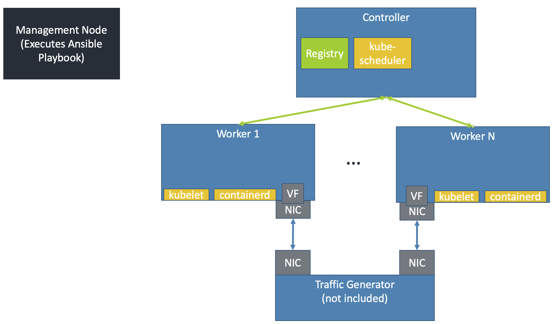
The Kubernetes cluster must have been set up by the create-cluster.yaml playbook. As shown, every worker node should be connected to the traffic generator & have PFs/VFs available to bind to application pod(s).
Get NIC PCIe Addresses
The PCIe address of the NIC connected to the traffic generator must be known for every worker. Additionally, the DPDK Linux driver for that NIC must be known. While this solution does support using multiple PCIe addresses on a single worker node, every PCIe address for a node must work with the same DPDK Linux driver. Different worker nodes may use different DPDK Linux drivers.
Ensure the PCIe addresses and DPDK Linux drivers for each worker are listed in the inventory file, as described in Create Ansible Inventory File.
Execute the DPDK-L3fwd Ansible Playbook
Execute the Ansible playbook in the <nw_cra_workspace>/cnf-reference-arch/examples/dpdk-l3fwd/ directory by running:
cd <nw_cra_workspace>/cnf-reference-arch/examples/dpdk-l3fwd/
ansible-playbook -i ../../inventory.ini dpdk-l3fwd.yaml
This playbook will execute the following steps:
Expands the DPDK deployment template to the controller node. By default, it will be placed at
~/dpdk-deployment.yaml.Generates a ConfigMap onto the controller node and adds it to the cluster. By default, it will be placed at
~/configmap.yaml.Copies files needed to build the
dpdkdocker image to temporary directory on the worker nodeOne worker node builds and pushes the image to the private docker registry on the controller node
The directory which hosts the dpdk-deployment.yaml and configmap.yaml files is controlled by the output_dir parameter.
To put those files in a different directory, add -e output_dir=path to the ansible-playbook command above. For example,
to place the files in ~/different_output_dir, the full command would look like:
ansible-playbook -i ../../inventory.ini dpdk-l3fwd.yaml -e output_dir=~/different_output_dir
Once the playbook successfully executes, ssh into the controller node and run:
cd <output_dir>
kubectl apply -f dpdk-deployment.yaml
This will create pods running the dpdk-l3fwd application. While the number of pods created equals the number of worker nodes, it is up to the Kubernetes
scheduler to decide on which nodes the pods will run.
Test
Monitor the application by running kubectl get pods on the controller node. It may take some time for the pods to start up. Once the pods are in the Running state, their logs can be viewed with kubectl logs <pod name>. The pod name can be obtained from the kubectl get pods command.
To get more information about the pods (such as which node it is running on), use kubectl get pods -o wide or kubectl describe pod <pod name>.
The logs of each pod should contain something similar to:
Initializing port 0 ... Creating queues: nb_rxq=1 nb_txq=1...
Address:98:03:9B:71:24:2E, Destination:02:00:00:00:00:00, Allocated mbuf pool on socket 0
LPM: Adding route 198.18.0.0 / 24 (0) [0001:01:00.0]
LPM: Adding route 2001:200:: / 64 (0) [0001:01:00.0]
txq=2,0,0
These logs show port 0 has MAC address 98:03:9B:71:24:2E with PCIe address
0001:01:00.0 on the worker node. 1 IPv4 route matching the subnet
198.18.0.0/24 is added.
Configure the traffic generator to send packets to the NIC port,
using the MAC and IP address displayed in the logs. In this example,
use a destination MAC address of 98:03:9B:71:24:2E and a destination
IP of 198.18.0.21. Then, dpdk-l3fwd will forward those packets out on port 0.
Stop
To stop the application pods, delete the deployment with kubectl delete deploy dpdk.
To clean up the K8s cluster, run sudo kubeadm reset -f and sudo rm -rf /etc/cni/net.d on controller and worker nodes.
Suggested Experiments
The example provided above covers a very simple use case of the DPDK L3fwd application. Users are encouraged to experiment with various options provided by the application.
Some experiments will involve changing the DPDK source code and/or the command line arguments to dpdk-l3fwd. Changes to these will require updating the deployed container image.
There are multiple ways to update the source code/executable in the sample application.
This guide recommends developing a patch locally & generate a patch file with git format-patch. The DPDK contributor guidelines have some examples on creating such a patch file.
Then, place the patch file in the <nw_cra_workspace>/cnf-reference-arch/examples/dpdk-l3fwd directory, and modify the dpdk-l3fwd.yaml playbook to copy the patch file to the workers. See the tasks copying the Dockerfile and dpdk-launch.sh files for reference. Finally, modify the Dockerfile to apply your patch (e.g. using git apply) before the ninja step.
Once the changes are in place, it is important they are used to generate an updated container image. To ensure the changes are always included, add force_source: yes to the docker_image task in dpdk-l3fwd.yaml. Once this is in place, an updated container image can be built at any time by re-running the dpdk-l3fwd.yaml playbook.
The users are also encouraged to try the following options to understand the performance and scalability possible with Arm platforms.
Number of RX/TX ring descriptors: This can affect the performance in multiple ways. For example, if the worker node is capable of storing the incoming packets in system cache, the incoming packets can trash the system cache, reducing the overall performance. To understand how these affect the performance, experiment by changing the number of descriptors. Change
RTE_TEST_RX_DESC_DEFAULTandRTE_TEST_TX_DESC_DEFAULTin filel3fwd.hand update the container image.--config: This parameter assigns the NIC RX queues to CPU cores. It is possible that a single queue might not be able to saturate a single CPU core. One can experiment by assigning multiple queues to a single core. For example, the option--config='(0,0,1),(0,1,1)'assigns the queues 0 and 1 of port 0 to lcore 1. Ensure that Receive Side Scaling (RSS) distributes the packets equally to all the enabled queues by sending multiple flows of traffic. Modify this parameter indpdk-launch.shand update the container image.CPU Scalability: Add more VFs to the deployment by increasing the
arm.com/dpdkand CPU requests/limits. Ensure the limits/requests for CPU and memory remain equal, otherwise the Pod will no longer be given dedicated CPUs. Additionally, update thek8s.v1.cni.cncf.io/networksannotation to repeatsriov-dpdkas many times asarm.com/dpdkis listed in the limits/requests sections. For example, to request 3 VFs for a single pod, then setk8s.v1.cni.cncf.io/networks: sriov-dpdk, sriov-dpdk, sriov-dpdkandarm.com/dpdk: 3for both limits and requests. Ensure that Receive Side Scaling (RSS) distributes the packets equally to all the enabled queues by sending multiple flows of traffic.Route Scalability: Add additional routes and multiple flows of traffic that exercise these routes. Additional routes can be added such that the accessed data size is more than the available L1, L2 or system cache size.
To change forwarding rules, edit the global constants in:
main.c: edit theipv4_l3fwd_route_arrayoripv6_l3fwd_route_arrayto adjust default routes for FIB or LPM lookup.
It is also possible to compile additional sample applications and run them following DPDK’s Sample Applications User Guide. To compile them, update the ninja step in the Dockerfile. To run them, modify dpdk-launch.sh accordingly.