User Guide
Introduction
Welcome to the CNF Reference Architecture user guide. This guide provides instructions on how to run a sample containerized networking application in a multi-node Kubernetes cluster comprised of AArch64 machines.
This reference solution is targeted for a networking software development or performance analysis engineer who has in-depth networking knowledge, but does not know AArch64 architecture necessarily.
Mastering knowledge on certain open source projects, e.g., Ansible, Kubernetes, DPDK, will help gain deeper understanding of this guide and reference solution more easily.
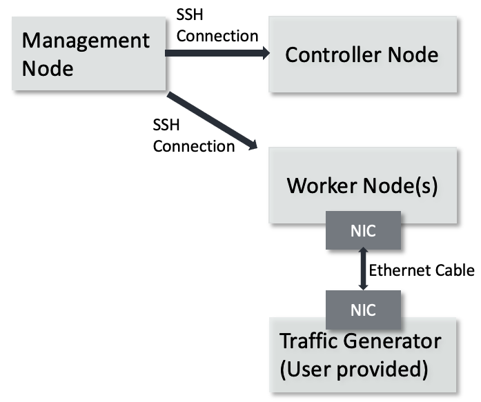
This guide is intended to describe complex and practical uses cases requiring complex test setup. By following the steps of this guide to the end, you will setup a multi-node Kubernetes cluster. One machine will serve as the Kubernetes controller and host a private Docker registry to hold custom container images. The worker nodes will run Application Pods, like DPDK L3 forward. The multi-node Kubernetes cluster topology is shown below.
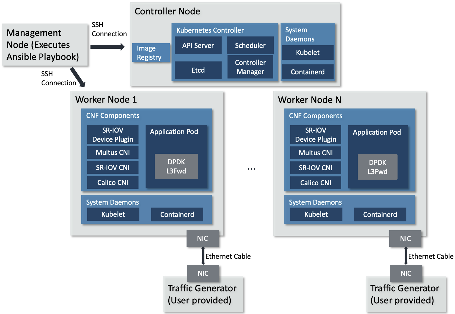
Multi-node Kubernetes cluster topology
The topology diagram above illustrates the major components of the deployment and their relationship.
DPDK L3 forwarding application, implements L3 networking function in software and forwards packets per their destination IP address.
TG (Traffic Generator), generates and sends packets to the worker node’s NIC card via the Ethernet cable. It can be hardware TG, e.g., IXIA chassis, or software TG running on regular server, e.g., TRex, DPDK Pktgen, Scapy.
Management Node, can be any bare-metal machine, VM, or container. It is used to download the project source code, login to the controller and worker nodes to create the Kubernetes cluster and deploy the application.
Hardware Setup
This guide requires the following setup:
Controller Node can be any machine that has a network connection to the other machines in the Kubernetes cluster. The solution is tested against an AArch64 machine as the controller node.
Hardware Minimum Requirements
The Controller Node has the following hardware requirements:
Minimum 1GHz and 2 CPU cores
Minimum 8GB RAM
Connection to the internet to download and install packages
Connection to the worker nodes
Software Minimum Requirements
The following items are expected of the Controller Node’s software environment:
Controller Node is running Ubuntu 20.04 (Focal)
Admin (root) privileges are required
The Fully Qualified Domain Name (FQDN) of the Controller Node can be checked with
python3 -c 'import socket; print(socket.getfqdn())'command. See FAQ if the proper FQDN is not shown.
Worker Nodes are any number of AArch64 architecture machines. NIC card is plugged into a PCIe slot and is connected to a traffic generator with an Ethernet cable.
Hardware Minimum Requirements
The Worker Nodes have the following hardware requirements:
AArch64 v8 CPU
Minimum 1GHz and 4 CPU cores
DPDK compatible NIC
Connection to the internet to download and install packages
Minimum 8G of RAM
Support 1G Hugepages
Software Minimum Requirements
Worker node is running Ubuntu 20.04 (Focal)
Admin (root) privileges are required
PCIe address of the NIC port(s) attached to the traffic generator is confirmed with
sudo lshw -C network -businfoCPU cores are isolated and 1GB hugepages reserved via required Linux command line parameters. See FAQ for more details.
There can be any number of worker nodes. To use a single-node cluster, refer to the Quickstart Guide.
Management node can be any bare-metal, VM, or container. The management node is used to download the repository, access the cluster nodes via
sshand configure the Kubernetes cluster by executing an Ansible playbook. The Ansible playbook is executed locally on management node and it configures the cluster nodes viassh.
Software Minimum Requirements
Can execute Ansible
Can
sshinto each cluster node using SSH keys. See FAQ for more details.Admin (root) or
sudoprivileges are required
TG can be any traffic generator capable of generating IP packets.
Tested Platforms
This solution is tested on the following platforms.
Cluster Nodes
Ampere Altra (Neoverse-N1)
Ubuntu 20.04.3 LTS (Focal Fossa)
NIC
-
OFED driver: MLNX_OFED_LINUX-5.4-3.1.0.0
Firmware version: 16.30.1004 (MT_0000000013).
Intel X710
Firmware version: 6.01
Note
To use Mellanox NIC, install OFED driver, update and configure NIC firmware by following the guidance in FAQ.
Management Node
Ubuntu 20.04 system
Python 3.8
Ansible 6.5.0
Prerequisite
Management Node
Management node needs to install dependencies, e.g., git, curl, python3.8, pip, Ansible, repo. Follow below guidelines on Ubuntu 20.04.
Make sure
sudois available and installgit, curl, python3.8, python3-pip, python-is-python3by executing$ sudo apt-get update $ sudo apt-get install git curl python3.8 -y $ sudo apt-get install python3-pip python-is-python3 -y
Install
ansibleby executing$ sudo python3 -m pip install ansible==6.5.0
Note
Install the
ansibleand not theansible-corepackage, as this solution makes use of community packages not included in theansible-corepython package.
Download Source Code
Unless mentioned specifically, all operations in this section are executed on management node.
Create a new folder that will be the workspace, henceforth referred to as
<nw_cra_workspace> in these instructions:
mkdir <nw_cra_workspace>
cd <nw_cra_workspace>
export NW_CRA_RELEASE=refs/tags/NW-CRA-2022.12.30
Note
Sometimes new features and additional bug fixes are made available in
the git repositories, but are not tagged yet as part of a release.
To pick up these latest changes, remove the
-b <release tag> option from the repo init command below.
However, please be aware that such untagged changes may not be formally
verified and should be considered unstable until they are tagged in an
official release.
To clone the repository, run the following commands:
repo init \
    -u https://git.gitlab.arm.com/arm-reference-solutions/arm-reference-solutions-manifest.git \
    -b ${NW_CRA_RELEASE} \
    -m cnf-reference-arch.xml
repo sync
Create Kubernetes Cluster
Unless mentioned specifically, all operations henceforth are executed on management node.
Create Ansible Inventory File
The Ansible playbooks in this repository are easiest to use with inventory files to keep track of the cluster nodes. For this solution we need one inventory file.
A template inventory.ini is provided at <nw_cra_workspace>/cnf-reference-arch/inventory.ini with the following contents:
[controller]
<fqdn> ansible_user=<remote_user>

[worker]
<fqdn> ansible_user=<remote_user> pcie_addr=<pcie_addr_from_lshw> dpdk_driver=<vfio-pci>
Under the [controller] heading, replace <fqdn> with the FQDN of the Controller Node. Under the [worker] heading, replace <fqdn> with the FQDN of a worker node, or an SSH destination for a worker node.
<remote_user> specifies the user name to use to login to that node.
Replace <pcie_addr_from_lshw> with the PCIe address of the port on the worker node connected to the traffic generator.
If the worker node uses Mellanox ConnectX-5 NIC to connect the traffic generator, replace <driver-name> with mlx5_core. Otherwise, replace it with vfio-pci.
If multiple worker nodes are to be used, each one should be a separate line under the worker tag, with ansible_user, pcie_addr and dpdk_driver filled in per worker node.
As an example, if the user name used to access the cluster nodes is user1, the controller’s FQDN is dut.arm.com, the sole worker is reachable at worker-1 and is connected to the traffic generator on PCIe address 0000:06:00.1 with a NIC compatible with the vfio-pci driver, then inventory.ini would contain:
[controller]
dut.arm.com ansible_user=user1

[worker]
worker-1 ansible_user=user1 pcie_addr=0000:06:00.1 dpdk_driver=vfio-pci
Note
All PCIe addresses for a single node must work with the same DPDK driver. This solution does not support per-address DPDK drivers without modification.
If worker-1 also had PCIe address 0000:06:00.0 connected to a traffic generator, then inventory.ini would contain:
[controller]
dut.arm.com ansible_user=user1

[worker]
worker-1 ansible_user=user1 pcie_addr="['0000:06:00.1', '0000:06:00.0']" dpdk_driver=vfio-pci
If the same setup also included a worker-2 which is connected to a traffic generator on PCIe address 0000:09:00.0 with a Mellanox NIC, then inventory.ini would contain:
[controller]
dut.arm.com ansible_user=user1

[worker]
worker-1 ansible_user=user1 pcie_addr="['0000:06:00.1', '0000:06:00.0']" dpdk_driver=vfio-pci
worker-2 ansible_user=user1 pcie_addr=0000:09:00.0 dpdk_driver=mlx5_core
Setup Kubernetes Cluster
Next, setup the Kubernetes cluster by executing the create-cluster.yaml playbook.
The playbook takes multiple override parameters that slightly modify its behavior.
To execute the playbook without any override parameters, run ansible-playbook -i inventory.ini -K create-cluster.yaml.
The playbook will operate in a few stages.
Stage 1: Install necessary packages and configuration
Install packages to use apt over HTTPS
Install python3 and pip
Install required python packages via pip
Add the Docker apt repository and install Docker CE
Add remote user to the docker group
Disable swap
Add Kubernetes apt repository and install Kubernetes packages
Clean up any prior K8s clusters
Configure
containerdto use systemd cgroups
Stage 2: Create and bind VFs
The playbook will create 2 VFs per PF and note the VF vendor/device ID for each worker node. It will also bind the VFs to the designated Linux driver for DPDK.
Stage 3: Create and trust a self-signed certificate
The playbook will create a self-signed certificate on the controller node, and have each node trust it. This is used by the docker registry to communicate over HTTPS.
Stage 4: Setup Kubernetes controller node
The playbook will perform the following steps on the controller node:
Start the Kubernetes control plane using
kubeadmAllow the controller node user to use
kubectlto interact with the clusterInstall Calico CNI
Copy the command to join worker nodes to the cluster to the management node
Start a private docker registry using the self-signed certificate
Generate and apply a configuration for the SR-IOV Device Manager
Install Multus CNI
Apply a Multus configuration
Stage 5: Setup the Kubernetes worker node(s)
The playbook will perform the following steps on the worker nodes:
Get a list of non-isolated CPUs
Join the Kubernetes cluster
Configure the kubelet to use the static CPU policy & dedicate isolated CPUs to Pods
Build an SR-IOV CNI image for Arm & push to the controller’s private registry (performed by only one worker node)
Install SR-IOV CNI
Install the SR-IOV Device Plugin
Override Options
This solution allows for modifying its behavior either by setting variables. To set certain variables at run-time, follow these docs.
Force VF creation
The default behavior of VF creation for a certain PCIe address would just try to create a certain number (2 by default) of VFs under it, but it may fail and show error like this:
echo: write error: Device or resource busy
which is due to existing VFs which have been created before.
To override this error condition, set the force_vf_creation to true, which would clear prior VFs before creating new VFs. Only set this option if the existing VFs are not used now.
The default value of force_vf_creation is false.
Skip VF creation
To skip VF creation, set the pcie_addr_is_vf variable to true. If VF creation is skipped, the PCIe addresses in the inventory.ini will be used directly by application pods. This differs from the default behavior where the supplied PCIe addresses are used to create VFs which are then dedicated to application pods.
Modify Pod CIDR
Each K8s Pod is assigned its own IP address. It is important the IP block for pods has no overlap with other IPs on the network. To change the Pod CIDR, set pod_cidr to an unoccupied CID.
Supply additional arguments to kubeadm init
Any additional arguments needed to be supplied to kubeadm init can be done so by setting kubeadm_init_extra_args to a string.
Use VFIO without IOMMU
When deploying to a platform without an IOMMU (like a virtual machine), the vfio-pci kernel module needs a parameter set. By setting no_iommu to 1, the playbook will take care of loading the kernel module properly.
Change number of VFs per PF
Set num_vfs to the number of VFs to create for each PF.
Self-signed certificate directory
Set cert_dir to place the self-signed certificates in the specified directory. By default, they will be placed in ~/certs on the controller node.
Timeout for Nodes to be Ready
Set node_wait_timeout to configure how long to wait for all K8s nodes to reach the Ready state. If any node is not ready by the end of the timeout, the playbook will exit with error. The wait occurs after joining worker nodes to the K8s cluster (if not a single-node cluster), but before building/installing the SR-IOV CNI.
The default is 600s, or 10 minutes.
Example
For example, the following command sets all possible overrides:
ansible-playbook -i inventory.ini -K create-cluster.yaml -e @vars.yaml
The -e parameter loads variables from the vars.yaml file. In this example, it contains:
pcie_addr_is_vf: true
pod_cidr: 192.168.54.0/24
kubeadm_init_extra_args: "--apiserver-advertise-address=\"192.168.0.24\" --apiserver-cert-extra-sans=\"192.168.0.24\""
no_iommu: 1
num_vfs: 5
cert_dir: ~/my-cert-dir
node_wait_timeout: "300s"
If the user is sure that VFs can be created on the desired PF PCIe address, a tag of force_vf_creation can be added and set to true when pcie_addr_is_vf is false:
force_vf_creation: true
Porting/Integrating to another Arm platform
Although the solution is tested on the platforms listed in the Tested Platforms section, the solution should work on other Arm platforms. However, such platforms should support Arm v8 architecture at least and be supported by the underlying components.